The Bike How-to
The following is a (very) rough how-to document explaining how to replicate my exercise bike project. It involves the purchase of exercise equipment, hobbyist wiring and Arduino microcontrollers. Exercise bikes range in price from the free unused ones in your marketing manager's closet, to a few hundred dollars. Arduino microcontroller kits are between $45-$60. When you consider the price of a gym membership around $50-$100 a month, it's not a bad investment :)
It helps, but isn't necessarily required to have knowledge on basic circuits, Arduino microcontrollers or embedded devices, computer programming, Linux and/or Windows command line, serial interfaces, and basic TCP/IP networking as it pertains to local ports. The project is, well, a little complicated to put together, but perhaps you have someone in your life that's into that kinda stuff? I'm willing to help with a few basic questions if problems arise and my documentation isn't helpful to you. I am super interested, however, in how people make better on the project, or find ways around problems they have. Godspeed, intrepid adventurers.
Step One
Acquire an exercise bike. Preferably one with an exposed and spinning wheel, and ideally one with a fixed gear mechanism (so you can't easily coast). My best results have been with a spin bike, made of mostly metal, and with almost all surfaces exposed. However, I've been able to modify the design to work with bikes without wheels at all, so don't distress just yet.
The Flux Capacitor
Acquire Arduino microcontroller and assorted electrical components. And Arduino is an open-source hardware platform, designed specifically to work well for hobbyists or amateur circuit designers. It can be programmed to drive circuits, or interact with other electrical / computing components as you see fit.
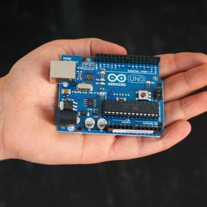
My project worked with a Duemilanove and its more recent incarnation, the Uno. Kits are available from a number of retailers. I initially chose the Hacktronics Educational kit. It came with everything except for the reed switches and the magnet.
Necessary for the project are:
- 1 Arduino microcontroller
- 1 Breadboard (I had the best luck with a full length one, but a half-length one works just as well)
- 4 solder-less jumpers/wires (1 for +5V, 1 for ground, 1 for signal a, 1 for signal b).
- 2 Reed Switches (ones that'll fit into a breadboard, and, just in case, I'd buy a few more than necessary, as they're fragile)
- 1 resistor (the 330 Ohm ones that came with the Educational Kit seem to suffice)
- 1 relatively strong magnet (capable of setting off reed switches at a distance of 1-2cm)
- 1 USB cable (recommend 6')If you end up using a Arduino clone, be sure to get one that supports at least 1 interrupt port for single signal setup, and 2 if you plan on setting up both signals (the slightly more complicated configuration).
While you're waiting for your Arduino to arrive, be sure to download the required software to talk to the Arduino. This package will include drivers, as well as a text editor / SDK to program the controller.
I've got these pieces...
So you've got a bike, some assorted electrical components, and enthusiasm. If you have some experience with electronics, or even designing simple DC electrical circuits, most of this should be a breeze. The things we're doing with these components aren't rocket surgery. Additionally, while I'm a little tech savvy, I'm mostly a computer programmer, and by no means an electrical engineer. Improvements can undoubtedly be made to the design. Feel free to modify as you see fit.
One thing to note at the beginning is placement of the bike itself. In the simplest of setups, you'll just be playing your movies on your poor laptop with the speakers cranked. This is fine, however, not all bikes have easy ways to hold laptops, nor is there necessarily the guarantee that you won't sweat on the laptop, or somehow knock it off trying some crazy move.
If you're planning on watching on your TV, the obvious recommendation is to be sure your bike is in good viewing distance of the TV, and also in a place that you can easily hear what's going on over the noise of the bike. Unless you have a 30' HDMI cable (which I eventually purchased), there's the added complication of having enough cord to connect the bike to your computer, and if you're using your television as a monitor, enough cord to get between your computer.
Here's what you're trying to replicate:
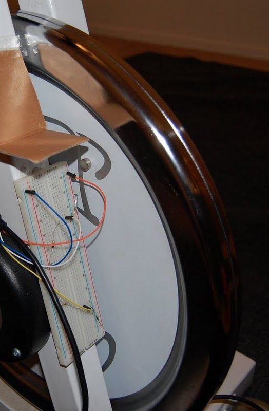
Don't judge my color choice, after building a few of these, I was short on choices:
- Orange: +5V
- Blue: Ground
- White: Signal A
- Yellow: Signal B
Mounting the breadboard and switches
The first thing is the mounting of the breadboard. The breadboards I've ordered online all seem to come with an adhesive backing that comes in handy. Placement, however, is a tricky thing. In my setup, I was able to find a sweet spot on the "fork" of the bike, such that if I centered the breadboard with the center of the bike wheel, I could then attach the magnet to a place on the inside of the wheel such that it would pass both of the breadboard's reed switches in a single rotation.
The breadboard should be mounted with the power rails closest to where the magnet will pass by the breadboard's edge. This is so that the reed switches, which will be hooked on one side to the power rails, can be triggered by the magnet as it goes by.
Getting both reed switches to trigger in a single rotation is a little difficult. You can usually tell if a reed switch triggers as you can hear its metal components inside touching and making the connection. If your breadboard is centered, I find that the easiest way to align the breadboard or the switches is to get one reed switch working such that the magnet is farthest away and will still trigger. After that, keep the breadboard in the same place, and rotate the wheel (with the magnet still attached). Find where the magnet passes by the breadboard again, and place the second reed switch there. Rotate the wheel by hand a few times to make sure you can hear both reed switches triggering. If both work, feel free to stick the breadboard to the bike in that place. Even if you make a mistake on the breadboard, you still have the option to move the switches along the power rail.
What if I don't have a wheel, or I can't get to it?
Not a big thing. If you don't have a wheel, or the wheel is enclosed such that you can't easily get a breadboard / switch close enough to it, you have the possibility of using the reed switches to measure pedal strokes. As long as you can ensure that where you place the components won't get sheered off by a stray foot, you should be good. I leave it to you to be creative, but as long as you're getting both signals as you go by, you should be good.
The Wiring
I'll say that the picture above is probably a better descriptor than anything I can muster here. However, I can explain what I'm doing for certain components, and where the wires are connected on the Arduino controller.
- Orange: Connected from the +5V on the Arduino controller to the power rail closest to the magnet. This is what will power each of the circuits, and provide the "logical true" signal to be interpreted by the controller.
- Blue: Connected to "GND" on the Arduino controller. Serves as ground.
- Reed Switches: Connected from the +5V power rail closest to the magnet to both a resistor to GND, and a signal wire. When the circuit is open (the magnet is not passing by either reed switch), the resistor to ground will keep the signal wire from "floating," that is, randomly triggering due to random interference.
- White: One of the signals connected between a reed switch and a resistor. Carries the signal from the reed switches to the interrupt ports (either of analog ports 2 or 3).
- Yellow: The other signal, connected to either analog port 2 or 3.
I have no idea if I did that correctly...
That's fine. Look again at the picture above. Does it look similar? Mostly? Well, once we load the software onto the Arduino, we'll have a pretty good idea if you wired it correctly or not.
But...
Listen. Everything will be alright. You have to trust me.
On to the Arduino controller
You downloaded the Arduino SDK, right? And installed the FTDI drivers, and the SDK that came with it? Good. Here's what I want you to do. Copy and paste the following into the SDK, and hit Upload:
int led_pin = 13;
int interrupt_pin_a = 0; // Digital pin #2
int interrupt_pin_b = 1; // Digital pin #3

int signal_pin_a    = 2; // Digital pin #2
int signal_pin_b    = 3; // Digital pin #3

volatile int state_a = 0;
volatile int state_b = 0;
volatile unsigned long last_seen_millis = 0;
volatile int pause_counter    = 0;
volatile int continue_counter = 0;

void setup(){
  noInterrupts();
  pinMode(led_pin,    OUTPUT);
  pinMode(signal_pin_a, INPUT );
  pinMode(signal_pin_b, INPUT );

  digitalWrite(led_pin, LOW);
  Serial.begin(9600);

  state_a = 0;
  state_b = 0;

  attachInterrupt(interrupt_pin_a, detect_a, RISING);
  attachInterrupt(interrupt_pin_b, detect_b, RISING);
  interrupts();

}

void detect_a() {
  noInterrupts();

  state_a++;

  interrupts();
}

void detect_b() {
  noInterrupts();

  state_b++;

  interrupts();
}

void loop(){
  if(state_a > 0 && state_b > 0) {
    // We saw a falling signal. This indicates
    // that the magnet sensor has gone past,
    // and we can issue a message over the serial
    // port.
    noInterrupts();
    state_a = 0;
    state_b = 0;

    // Indicate signal with LED
    digitalWrite(led_pin, HIGH);
    Serial.println( millis() );
    digitalWrite(led_pin, LOW);
    interrupts();

    last_seen_millis = millis();
    // Wait at least 100 milliseconds
    // before trying to detect the next interrupt
    while( millis() < ( last_seen_millis + 100 ) ) {
      state_a = 0;
      state_b = 0;
    }
  }

  // We don't see an interrupt from state_a, but
  // we should check if we've left the sensor
  // in pause mode
  while( digitalRead(signal_pin_a) ) {

    digitalWrite(led_pin, HIGH);

    last_seen_millis = millis();
    // Wait at least 100 milliseconds
    // before trying to see if we're
    // paused
    while( millis() < ( last_seen_millis + 100 ) ) {
      // Noop
    }

    // We've waited 100 milliseconds and we're still
    // reading positive signal
    pause_counter++;

    // If we've seen this behavior for 5 seconds,
    // pause the exercise.
    if(pause_counter > 50) {
      Serial.println( "pause" );
      last_seen_millis = millis();
      while( millis() < ( last_seen_millis + 10000 ) ) {
        // Noop
      }
    }
  }
  pause_counter = 0;
  digitalWrite(led_pin, LOW);

  // We don't see an interrupt from state_b, but
  // we should check if we've left the sensor
  // in continue mode
  while( digitalRead(signal_pin_b) ) {

    digitalWrite(led_pin, HIGH);

    last_seen_millis = millis();
    // Wait at least 100 milliseconds
    // before trying to see if we're
    // paused
    while( millis() < ( last_seen_millis + 100 ) ) {
      // Noop
    }

    // We've waited 100 milliseconds and we're still
    // reading positive signal
    continue_counter++;

    // If we've seen this behavior for 5 seconds,
    // pause the exercise.
    if(continue_counter > 50) {
      Serial.println( "continue" );
      last_seen_millis = millis();
      while( millis() < ( last_seen_millis + 10000 ) ) {
        // Noop
      }
    }
  }
  continue_counter = 0;

  digitalWrite(led_pin, LOW);

}
The above shows the code required to power the Arduino controller.
Something bad happened.
Did your code fail to upload? Or your Arduino failed to initialize? Check to see that you have the right Arduino board selected on the Arduino SDK.
Oh, okay. Code uploaded.
The idea behind the code is the following:
- Listen on interrupts 0 and 1 for a rising signal (interrupts 0 and 1 are analog inputs 2 and 3, respectively, on the Arduino controller). These detect when Signal A or Signal B come in from the breadboard, and increment the state counters for either Signal A or Signal B.
- If we've seen Signal A (state A is > 0) and we've seen Signal B (state B > 0), we've effectively seen one rotation. This, of course, depends on the placement of your breadboard, the distance between your reed switches, etc., but for the purposes of the program, this is probably the best measurement of whether you're riding the bike. If we see a rotation, send the current time in milliseconds over the USB serial connection.
- If we've seen Signal A for longer than 5 seconds, send the string "pause" to the serial port. Stop sending pause once we see we're no longer seeing Signal A. This represents "pause" mode, which should trigger the driving program running on the computer to go into "pause" mode, pausing both the exercise and the video it's playing.
- If we've seen Signal B for longer than 5 seconds, send the string "continue" to the serial port. Stop sending pause once we see we're no longer seeing Signal B. This represents "other exercise" mode, which should trigger the driving program running on the computer to go into "other exercise" mode, stopping the exercise, but keeping the video playing.
Once you've uploaded your code, you'll want to test to make sure this is working. Using the Arduino SDK, bring up the serial port. Make sure you're connected to the right serial port. On Mac/Linux, your port will be something like /dev/tty.XYZ. On Windows, it will be something like COM3, COM4, etc. See the Arduino documentation to get a better idea.
Move the wheel past the two sensors. You should see an integer number come up on the serial monitor. If you continue to rotate the wheel, you should see ever-increasing numbers. If this works, then you're likely in good shape.
Next, hold your wheel such that the magnet is right next to one of the reed switches. If after 5 seconds you see either "pause" or "continue", then you'll be able to successfully enter "pause" or "other exercise" mode. Note which of the sensors corresponds to this mode, and then make sure the other switch works for the opposite mode.
You see a bunch of random numbers, pause, and continue in the serial monitor output? That's great!
No, I'm missing something. Your careless words have lead me astray.
Alright, Bold Text. What's happening?
It doesn't matter if I'm spinning the wheel, the numbers just appear randomly.
Check your connections to ground. If not properly grounded, your signal wires will randomly fire due to movement of the wires, movement of the bike, and radio interference.
I'm not seeing anything come back on the serial monitor.
Well, make sure your Arduino is plugged in. Then, check to make sure you have the right serial port selected in the Arduino SDK. It's usually the first serial port on the list that the Arduino SDK gave you, but it might not be the case. Also, there's the distinct possibility that your user doesn't have permissions to access serial ports. This is sort of a quagmire of problems, made even more challenging in trying to troubleshoot across different operating systems. If you want, try other Arduino programs, or preferably programs that don't require connecting to a circuit, or ones that'll just test out the serial port. The Arduino SDK has a number of examples, and I'm sure you can find a few online to make sure everything is alright.
Ok, whatever. It works. I've now spent hours on this when I could have been watching Jersey Shore.
You are perpetuating a culture bereft of creative and cultural dignity. I expected more from you. But, once you finish this, you'll be able to bike while you're watching, so that's something.
On to your computer.
The Computer
You've successfully wired your bike, and verified output from the Arduino controller. Congratulations. Now, we just have to provide the glue between your Arduino's output and your video playback. That glue is in the form of a Perl script.
You can find the Perl script for Linux and Mac OS X here. You can find the script for Windows here. Extract these archives into a well-known folder somewhere on your computer. Then, within the exercise.pl file, find the following line:
//On Linux/Mac OS X
use lib '/home/someone/exercise/';

//On Windows
use lib 'C:\\Users\\someone\\exercise';
These lines represent where our Perl scripts will look for our library files. If you noticed when you extracted the exercise Perl scripts, there was a .pm file called VLCInterface.pm. This file is important, in that it is used by the exercise.pl script to talk to VLC. This use lib line points to the directory that contains the VLCInterface.pm file. This must be set, otherwise the running Perl script will have no idea where to find the VLCInterface.pm file.
While we've defined a VLCInterface module, we also need a few other modules to properly read from our Arduino controller. For Windows, Mac, and Linux, most Perl installations come with built-in standard modules that you won't have to worry about tracking down. For the exercise bike, though, we'll need a module that takes care of talking to the serial port.
On Linux / Mac OS X, you'll need to track down the Device::SerialPort module. It is available through CPAN, and can be installed using a tool called CPAN. These can be found on almost any *nix system. Shell commands will be the following:
sudo cpan install Device::SerialPort
Sadly, on Windows things are more complicated. Perl does not come standard with any version of Windows. However, a company named ActiveState has a free-ish product called ActivePerl, with an included package manger called "ppm." They do a pretty good job maintaining a repository of Windows ports of the most popular/useful Perl modules. On the Windows side of things, you need the Win32::SerialPort module. This is an (almost) drop-in replacement for the functionality provided by Device::SerialPort.
Download ActivePerl here. Make sure you get the 32-bit version, as of this writing, there's no 64-bit version of Win32::SerialPort. Make sure you install the Perl Package Manager (ppm).
Once complete, we need to grab the Win32::SerialPort module. Open a command prompt by hitting Windows-R, typing "cmd" and hitting enter. This will bring up a command prompt. In it, type this:
ppm install http://www.bribes.org/perl/ppm/Win32-SerialPort.ppd
This will install the correct Win32::SerialPort device module. You may have to be running in Administrator mode on the console.
Once you have modified exercise.pl to point to the right directory for VLCInterface.pm, and installed either Device::SerialPort or Win32::Serial port, open up another command prompt. Use Perl to tell us whether we're going to be able to successfully run the Perl script in the next few steps.
On Linux:
perl -c /path/to/exercise/exercise.pl
On Windows:
perl -c c:\path\to\exercise\exercise.pl
If the Perl interpreter comes back without any errors, then your exercise.pl script is ready to run.
One final configuration thing to note. Remember when we were looking at the serial monitor on the Arduino? And we had you find the right serial port so we could listen on that port? Remember which port that was?
If you don't, head back to the Arduino SDK and poke around until you find it. Otherwise, specify using the --serial-port=/dev/tty.something flag to indicate which serial port you want to point to. If you're feeling brave, feel free to edit this in the exercise.pl script to be the default.
Configuring VLC
VLC Media Player is a wonderful piece of software. And it has a number of fun interfaces that make it programmable. The interface we're using is the telnet interface, which has VLC listen on a given TCP port for textual commands.
The first step to take is enabling the telnet interface. In VLC, find the Preferences screen. In the Preferences screen, make sure you view the "Advanced" settings for the application, or "All" of the settings. Under the Interface settings, select Main Interfaces, then RC. Make sure "Fake TTY" is selected, and TCP command input has the value "0.0.0.0:4142". Then, back under the Main Interfaces settings, make sure that the Remote Control interface is selected. "rc" should appear in the text box. This might also be called the "oldtelnet" module, depending on the version of VLC you're using.
Second, we need to enable the "marquee" video overlay feature. This will let us write text over our video so we can see how well we're doing in our workout. Again in the advanced Preferences setting, under Video > Subtitles / OSD > Marquee. Remove "VLC" from the Text field, and put the Marquee position as "Top Right" (or anything but center). Then, on the Subtitles / OSD setting section, click on "Marquee display" under Overlays to enable the Marquee module.
Hit Apply. Quit VLC, and start it up again. You should be able to telnet to port 4142 on localhost and issue commands via a command line interface to VLC. This is the same interface that the Perl script will use. Only one client can be connected to the VLC telnet interface at one time, so make sure you disconnect from the telnet window before running the exercise.pl script.
Bike Bike Bike
Finally. You've got the Arduino programmed, the Perl script configured, and VLC set to listen.
Now, on Linux and Mac OS X, order of operations doesn't seem to matter quite as much as far as whether you start VLC first or the exercise.pl script first. The exercise.pl Perl script is smart enough to wait for VLC. On Windows, however, there's possibly an unidentified bug which forces you to start VLC media player first. Further research is required, but I just get angry and bigoted whenever I'm working on Windows.
When you first start up, VLC should start displaying exercise stats on the marquee you configured, over the video you're playing. If it doesn't, or if the script indicates that it's waiting for the serial port, or the connection to VLC, you may have your paths crossed somewhere.
To start the exercisxe.pl script on Linux or Mac OS X, in a terminal, perform the following command in a terminal window:
perl /path/to/exercise/exercise.pl
To start the exercise.pl script on Windows, open an Administrator prompt window and perform the following with your own corresponding path to the exercise.pl script:
perl C:\path\to\exercise\exercise.pl
If things are working, exercise.pl will start ticking away steps. Each step is a second, and for the RPMs you want, exercise.pl will maintain the number of RPMs you desired for each step of the program. When first starting up, you have no RPMs, and so exercise.pl stops the video and kicks it out of fullscreen. The default RPMs is 120rpm. This works well if your sensor is attached to a bike which that spins twice for every one pedal. If you have different gearing, or your sensors are sensing the passing of your pedal, you probably want to change this. The flag for that is --desired-frequency=60